
Redacted sample · free PDF · no email required
Sample Arc Flash Study Report
A redacted excerpt built on the same template as our sealed studies. The tables are real model output from completed projects, with every client and equipment identifier removed. Read it here or download the PDF.
What’s inside an arc flash study report
Every report follows the same structure, whether the site is a hospital, a water reclamation plant or a distribution center. Here is what each section is for.
- 1
Executive summary
One to two pages: scope, where the data came from, and the headline result of each study — maximum fault current, under-rated equipment, coordination problems, incident-energy range and the number of DANGER locations.
- 2
System overview, methods & assumptions
A narrative of your distribution system, the software and modules used (SKM Power*Tools), and every assumption written out — utility data margin, cable lengths, inaccessible devices — so an auditor or the next engineer can follow the model.
- 3
Short circuit & equipment evaluation
Available fault current at every bus for each operating scenario, checked against each device's interrupting rating and each assembly's SCCR (NEC 110.9 / 110.10). Under-rated equipment is listed with a specific fix.
- 4
Protective device coordination
Time-current curves from the utility fuse down, existing vs. proposed settings tables your electricians can dial in directly, and a narrative of each coordination finding.
- 5
Arc flash hazard analysis
IEEE 1584-2018 incident energy, arc flash boundary and working distance for every location, the controlling scenario, sample WARNING / DANGER labels, and NFPA 70E PPE guidance.
- 6
Recommendations & mitigation
What to change and in what order — settings, replacements, maintenance switches, de-energized work rules — tied back to the finding that drives each one.
- A
Appendices
Field-verified one-line with fault current at each bus, utility correspondence, photographs, and the full SKM input/output reports. Load flow, voltage drop and motor starting sections are added when they are in scope.

Sealed report, bound and digital
Sealed by the PE licensed in your facility’s state. The study date is the first thing an auditor looks for.
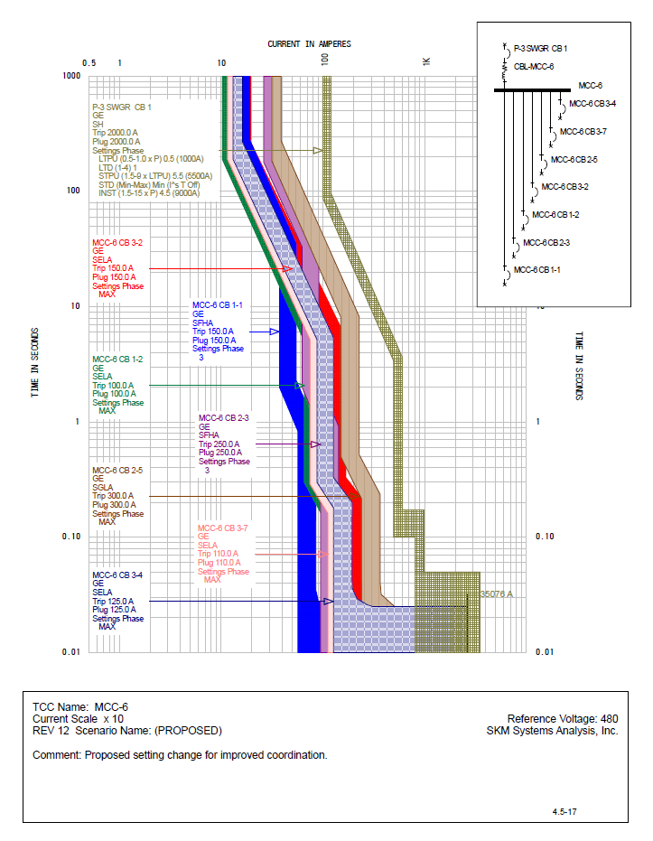
Time-current curves & proposed settings
Coordination drives clearing time, and clearing time drives incident energy. Proposed settings come as a table your electricians can dial in.
Sample incident energy table (IEEE 1584-2018)
One row per location. These twelve rows are real SKM Power*Tools output from completed PowerSafe studies, with the tags renamed. Your electricians and EHS team work from this table, and it’s the data printed on each label.
The two DANGER rows sit upstream of every customer-owned device, so only the utility’s primary fuse can clear them and the arc runs to the 2-second limit. The report’s answer is a de-energized work rule, because no amount of PPE fixes that.
Bolted / arcing kA
Bolted fault current is the theoretical maximum. Arcing current is lower, and it is what actually determines how fast the protective device clears the arc.
Incident energy (cal/cm²)
Heat energy at the worker's face and chest at the working distance. It sets the minimum arc rating of the clothing. Above 40 cal/cm², we recommend de-energizing.
Arc flash boundary
The distance at which incident energy falls to 1.2 cal/cm², the onset of a second-degree burn. Anyone inside it needs arc-rated PPE.
Working distance · box size
IEEE 1584-2018 corrects the result for enclosure size and the electrode configuration (VCB, VCBB, HCB, VOA, HOA), which is why we measure the gear and don't assume it.
DANGER vs WARNING
DANGER means more than 40 cal/cm², where no energized work is permitted. In real studies, that location is usually the service line side, which only the utility's fuse can clear.
What our arc flash studies typically find
These patterns come from our completed reports. They are why a label table alone, with no coordination or equipment evaluation behind it, misses most of the value.
The worst hazard is usually upstream of everything you own
When a facility has a DANGER (>40 cal/cm²) location, it is almost always the service-entrance line side or a fire pump controller fed straight from the utility transformer. Only the utility's primary fuse can clear it, so the arc runs to the 2-second limit. The answer is a de-energized work rule there, not heavier PPE.
Under-rated equipment turns up in about half our studies
Typically 14 kA or 18 kA panel breakers seeing 22–36 kA of available fault current after a utility upgrade or a larger transformer. We check for a tested series rating first (NEC 240.86) before anyone recommends replacing gear.
Breakers left at factory default settings
Electronic-trip breakers are routinely found at their out-of-box settings, so they neither coordinate nor limit incident energy. A settings table is often the cheapest hazard reduction in the whole report.
Generator power raises incident energy
On generator, arcing current can fall below short-time and instantaneous pickups, so clearing slows down and incident energy climbs. We model both sources, report the worse case, and recommend dual settings groups or a maintenance switch where it matters.
Labels installed on your equipment
Printed on a substrate suited to the environment and placed where a worker will actually read it. We don’t ship them in an envelope for you to sort out. Labels are valid only once the proposed settings are implemented, and the report says so.
Appropriate PPE Required
PowerSafe Engineering, LLC
The label itself
Every field NFPA 70E 130.5(H) requires, plus the study date. Print-ready files are included so you can replace damaged labels yourself.
Where these reports come from
39 PowerSafe projects since 2022, across Georgia and the Southeast. Client names are confidential. The mix by sector:
Water & wastewater utilities
Treatment plants, reclamation facilities, wells, pump stations, elevated tanks
Industrial & manufacturing
Food and poultry processing, packaging, beverage, equipment manufacturing
Commercial, institutional & distribution
Distribution centers, retail redevelopment, offices, churches, camps, port facility
Healthcare
Critical-access hospital; healthcare central utility plant
See the engineering in detail: case studies water & wastewater studies
What do you need the report for?
My facility needs a study
You need a first study, or your current one is over five years old or predates a system change. Get a written fixed-fee scope.
I’m specifying or subcontracting one
You’re a contractor, MEP firm or design engineer with a study section in the specs. We work as your study subconsultant.
I have a study. Is it still valid?
Send the date, the standard it cites (IEEE 1584-2002 or 2018), and any changes since. A PE will tell you whether it needs an update or a full redo.
Need a complete report for your sector?
The PDF is an excerpt. If you’re writing an RFP or comparing vendors, tell us your facility type and we’ll send a complete redacted study from a similar facility, with all the curves, settings sheets and appendices.
Or call (571) 310-6945
Just want the excerpt? Download the PDF. No form required.
Sample report FAQ
Related: arc flash study services, label requirements, and how to prepare for a study.
At minimum: the system model's assumptions and data sources, a short circuit analysis with equipment duty evaluation, the protective device coordination that produces clearing times, incident energy and arc flash boundary for every location per IEEE 1584-2018, label data that meets NFPA 70E 130.5(H), and recommendations. If a report only has a label table, the clearing times behind it were never checked.
Our sealed reports run roughly 22 to 80 pages, depending on how many locations are studied and whether coordination, load flow, or motor starting is in scope. Most of the length is SKM output and time-current curves. The executive summary and recommendations are what management reads.
No. Incident energy depends on your utility's available fault current, your transformers, cable lengths, and the actual trip settings of your breakers. Two identical-looking panels can differ by a factor of ten. The sample shows format and depth, not numbers you can use.
No. The sample is an unsealed, redacted excerpt. Every real PowerSafe study is reviewed and sealed by a professional engineer licensed in the state where the facility is located.
Yes. Many owners and design engineers use the section list to define deliverables for an RFP. If you are writing a spec for a construction project, we can also review your study section before bid.
NFPA 70E 130.5 requires the arc flash risk assessment to be reviewed at least every five years, and whenever a change could affect the results. A new utility transformer, added generation, or changed breaker settings are common triggers.
Find out where your facility stands.
A 10-minute call with a licensed PE — we'll tell you what your study should cover and what it should cost. No obligation.